
UHF Folded Dipoles & Yagis – Standard Series
UHF Yagis & Folded Dipoles
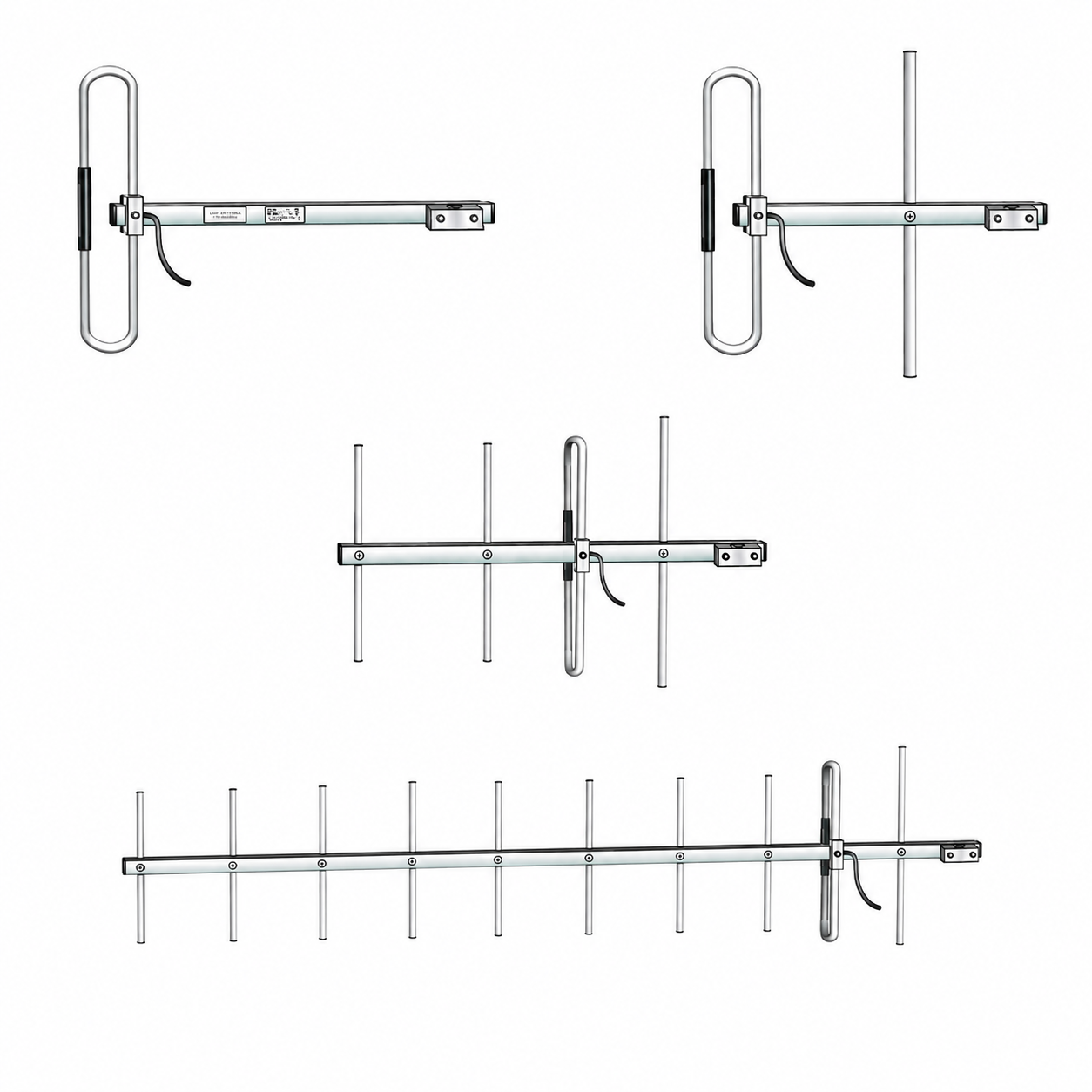
A standard range of lightweight UHF yagis and folded dipoles designed for urban and rural site installations. Models include folded dipole and yagi options, providing reliable performance while keeping wind loading and support requirements low.
Constructed from Grade 6000 series aluminium with a silver anodised finish for improved corrosion resistance, these antennas feature robust extruded elements and a square tube boom. The matching section is sealed within the driven element, eliminating the need for an external balun, and all elements are DC grounded.
Vertical polarisation mounting is standard, with clamp options available for 25mm, 38mm, 48mm or 63mm outside diameters. The universal clamp also allows flexible mounting for either vertical or horizontal polarisation.
Models FDU & Y2U to Y12U
The standard range of UHF yagis and folded dipoles are designed for urban or rural site installations. Being lightweight with small projected surface areas, they can be installed on low cost supports. The coding “FD” indicates Folded Dipole and “Y” indicates Yagi.
These antennas are constructed from Grade 6000 series aluminium. Corrosion resistance is increased by silver finished anodising. Elements are 12.7 x 1.42mm extruded sections, which provide a robust antenna. The boom section is 25 x 25 x 1.8mm square tube, to which the driven element is clamped. The parasitic elements are fitted through the boom and fixed with aluminium rivets.
The nominal feed impedance is 50 ohms with the matching section sealed within the driven element, eliminating the need for an external balun. All elements are D.C. grounded.
Mounting for vertical polarisation is standard. Mounting options available for clamping to 25mm, 38mm, 48mm or 63mm outside diameters include the mounting clamps, saddle clamps or the universal clamp. The universal clamp provides flexibility in mounting for either vertical or horizontal polarisation.
| Model | FDU | Y2U | Y3U | Y4U | Y6U | Y8U | Y10U | Y12U |
| Number of Elements | 1 | 2 | 3 | 4 | 6 | 8 | 10 | 12 |
| Frequency Range (MHz) | 400-505 (see bandwidth) | 400-495 (see bandwidth) | ||||||
| Bandwidth (MHz) | 100 | 50 | 20 | 50 | 30 | 30 | 20 | 20 |
| Gain (dBd) | 0 | 3 | 4.5 | 6.5 | 8 | 9 | 10 | 11 |
| Half Power Beamwidth E Plane (deg) | N/A | 75 | 67 | 60 | 50 | 40 | 35 | 33 |
| Half Power Beamwidth H Plane (deg) | N/A | 145 | 114 | 85 | 42 | 43 | 37 | 36 |
| Front to Back Ratio (dB) | 0 | 10 | 15 | 20 | 20 | 20 | 20 | 20 |
| Input Impendance (Ohms) | 50 | |||||||
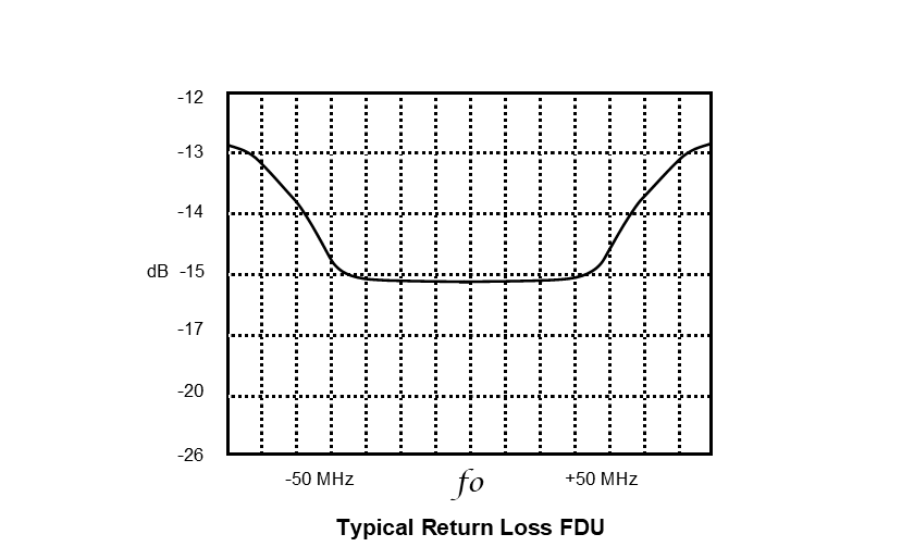
| Return Loss (dB & VSWR) | <-14dB 1.5:1 | |||||||
| Maximum Power (W) | 100 | |||||||
| Cable Type | RG58 or RG58LL | |||||||
| Max Element Length (mm) | 320 | 400 | ||||||
| Boom Length (mm) | 375 | 300 | 400 | 600 | 980 | 1350 | 1700 | 1900 |
| Boom Diameter (mm) | 25mm square | |||||||
| Projected area (m2) | 0.02 | 0.023 | 0.03 | 0.04 | 0.058 | 0.076 | 0.094 | 0.108 |
| Weight (kg) | 0.6 | 0.6 | 0.7 | 0.8 | 2 | 1.2 | 1.4 | 1.55 |
| Mounting Location | Rear | |||||||